Thermal Design Best Practices for EV Chargers

Designing thermal management systems for EV chargers requires careful consideration of power density, ambient conditions, and reliability requirements. With DC fast chargers pushing 350kW and beyond, thermal design has become one of the most critical aspects of charger development. In this comprehensive guide, we'll explore the key thermal challenges and proven solutions for EV charger design.
Understanding the Thermal Challenge
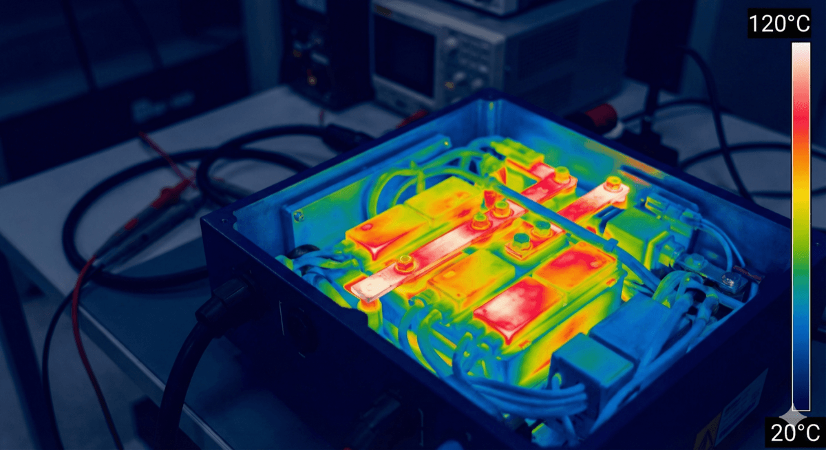
EV chargers face unique thermal challenges that distinguish them from other power electronics applications. Unlike stationary indoor equipment, chargers must operate reliably across extreme temperature ranges—from -30°C in Minnesota winters to +50°C in Arizona summers. The power electronics inside, including IGBTs, MOSFETs, inductors, and capacitors, generate significant heat that must be efficiently dissipated to maintain junction temperatures within safe operating limits.
A 350kW DC fast charger typically dissipates 10-15kW of heat at full load, assuming 95-97% efficiency. This heat is concentrated in a relatively small volume, creating localized hot spots that can quickly lead to component degradation if not properly managed. The challenge is compounded by the intermittent nature of charging sessions—thermal cycling from ambient to full-load temperatures creates mechanical stress that accelerates fatigue failures in solder joints and wire bonds.
Component Placement Strategy
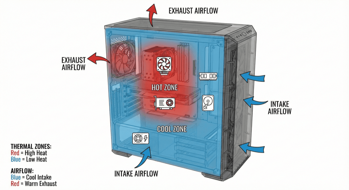
Smart component placement is the foundation of effective thermal design. The goal is to minimize thermal coupling between heat sources while optimizing airflow or coolant paths. Key strategies include:
Separate high-power and control electronics: Power semiconductors operating at elevated temperatures can affect the reliability and accuracy of nearby control circuitry. Maintain physical separation and use thermal barriers where needed.
Orient components for optimal heat flow: Position power modules so heat can flow directly to heatsinks or cold plates without passing through PCB substrates or other components. Vertical mounting often improves natural convection.
Consider thermal symmetry: In multi-phase designs, arrange power stages symmetrically to ensure even temperature distribution. Uneven heating leads to current imbalance and reduced overall capacity.
Plan for serviceability: Components that may need replacement (fans, capacitors) should be accessible without disturbing the thermal interface of critical power components.
Thermal Interface Material Selection
The interface between power devices and heatsinks is often the weakest link in the thermal chain. Even microscopic air gaps create significant thermal resistance—air has a thermal conductivity of just 0.026 W/mK compared to 200+ W/mK for aluminum. Thermal interface materials (TIMs) fill these gaps to minimize contact resistance.
For EV charger applications, consider these factors when selecting TIMs:
Thermal conductivity: Higher is generally better, but diminishing returns occur above 5-10 W/mK for most applications. A 3 W/mK pad may perform nearly as well as a 10 W/mK pad once contact resistance is accounted for.
Bond line thickness: Thinner is better for thermal performance, but you need enough thickness to accommodate surface flatness tolerances. Typical gaps range from 0.1-0.5mm.
Long-term stability: Thermal greases can pump out under thermal cycling. Phase-change materials or gap pads may be more reliable for automotive-grade applications requiring 10+ year lifetimes.
Assembly considerations: Pads are easier to apply consistently in production than greases. Consider the impact on manufacturing yield and rework procedures.
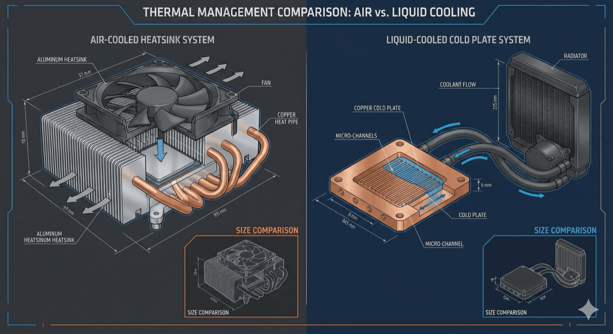
Cooling System Selection: Air vs Liquid
The choice between air and liquid cooling fundamentally shapes the charger's architecture, cost, and reliability profile.
Air cooling is simpler and less expensive for chargers up to approximately 100-150kW. Forced-air systems using axial or centrifugal fans can achieve heat transfer coefficients of 50-150 W/m²K. However, air cooling has limitations: fans are the most common failure point in power electronics, and performance degrades significantly at high ambient temperatures when the temperature differential shrinks.
Liquid cooling becomes attractive above 150kW where air cooling would require impractically large heatsinks. Cold plates with optimized internal channels can achieve thermal resistances below 0.05°C/W—an order of magnitude better than air-cooled heatsinks. Liquid systems also enable more compact designs by decoupling heat generation from heat rejection.
The trade-offs include added complexity (pumps, reservoirs, heat exchangers), potential leak risks, and higher system cost. However, for premium fast chargers targeting 10-15 year outdoor deployment, liquid cooling often proves more reliable than air systems with their failure-prone fans and filters.
CFD Simulation Best Practices
Computational Fluid Dynamics (CFD) simulation is essential for optimizing EV charger thermal design before committing to hardware. Effective simulation requires attention to several key areas:
Model fidelity: Include all significant heat sources, not just power semiconductors. Inductors, capacitors, busbars, and even control boards contribute to the thermal load. Simplify geometry where possible but preserve flow-critical features.
Boundary conditions: Use realistic ambient conditions representing worst-case deployment scenarios. For outdoor chargers, consider solar loading (up to 1000 W/m² on sun-facing surfaces) and reduced convection in enclosed installations.
Mesh quality: Power electronics thermal simulations require fine mesh resolution near heat sources and interfaces. Use inflation layers on walls and mesh refinement in critical regions. Verify mesh independence by comparing results at different mesh densities.
Validation: Always correlate simulation results with thermal measurements on prototypes. Adjust model parameters (contact resistances, material properties) to match measured data before using the model for design optimization.
Design for Reliability
EV chargers must operate reliably for 10-15 years in demanding outdoor environments. Thermal design directly impacts long-term reliability through several mechanisms:
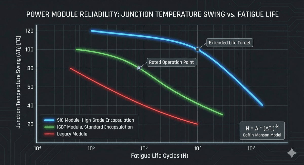
Thermal cycling fatigue: Each charging session creates a thermal cycle that stresses solder joints and wire bonds. Design for junction temperature swings below 40°C to maximize fatigue life. Use simulation to predict cycle counts and compare against component fatigue curves.
Derating: Never operate components at their absolute maximum ratings. Apply appropriate derating factors—typically 70-80% of maximum rated temperature—to provide margin for manufacturing variation, aging, and unexpected operating conditions.
Redundancy: For critical applications, consider N+1 redundancy in cooling systems. Dual fans or pumps allow continued operation (at reduced capacity) if one unit fails.
Monitoring: Integrate temperature sensors at critical locations to enable thermal protection and predictive maintenance. NTC thermistors near power modules can trigger load reduction before damage occurs.
Conclusion and Key Takeaways
Successful thermal design for EV chargers requires a systematic approach that considers the complete thermal path from junction to ambient. Key takeaways include:
-
Start thermal design early in the development process—retrofitting cooling solutions is always more expensive than designing them in from the start.
-
Use CFD simulation to optimize designs before building hardware, but always validate with thermal measurements.
-
Select cooling technology (air vs liquid) based on power level, deployment environment, and reliability requirements rather than just cost.
-
Pay careful attention to thermal interfaces—they often limit overall thermal performance more than heatsink or cold plate design.
-
Design for the worst-case operating conditions with appropriate derating to ensure long-term reliability.
By following these principles, you can develop EV charger thermal systems that meet performance requirements while delivering the reliability that operators and vehicle owners expect.
Free Resource: Download our Thermal Design Checklist for an 8-page guide covering all critical thermal design considerations for power electronics.