Liquid Cooling for AI Infrastructure: From Rack to Chip
Direct-to-chip liquid cooling has emerged as the only viable solution for next-generation AI accelerators. With GPUs pushing past 700W and heading toward 1000W, the thermal path from silicon die to ultimate heat rejection requires engineering precision at every step. This guide examines liquid cooling architectures from chip-level cold plates through facility-level heat rejection, covering the design principles and practical challenges of deploying liquid cooling for AI infrastructure.
The Thermal Path in Liquid-Cooled AI Systems
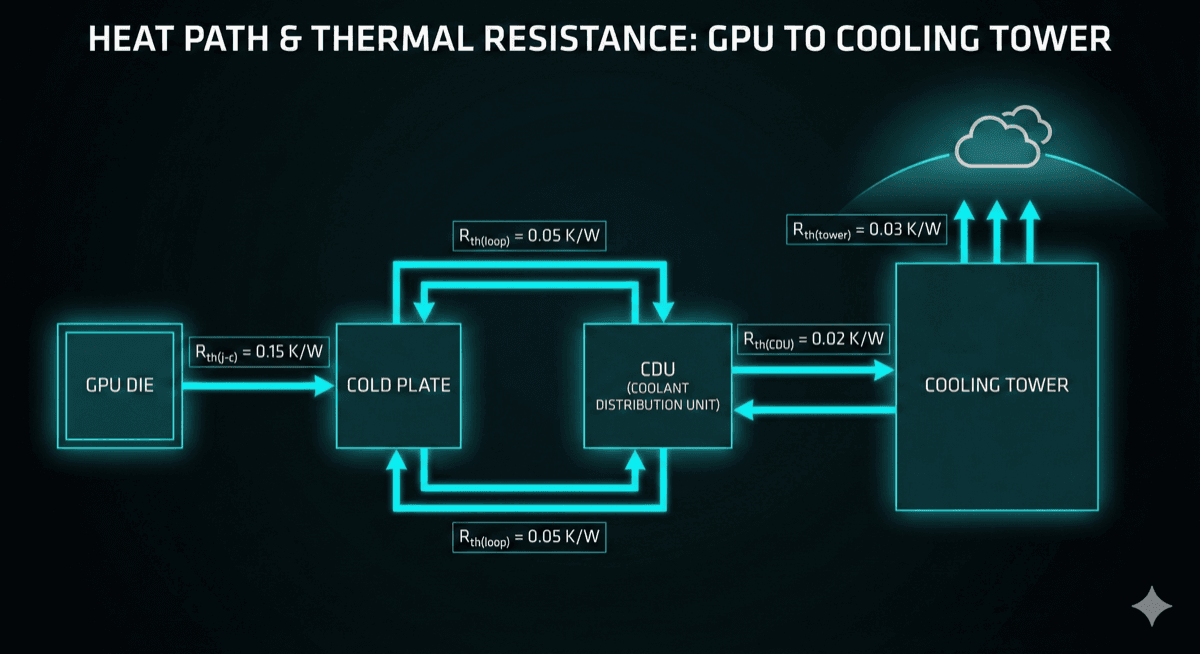
Understanding the complete thermal path is essential for effective liquid cooling design. Heat must travel from the GPU die through multiple interfaces and systems before rejection to the environment:
-
Die to Package: The GPU die connects to its package substrate via thermal interface material or direct copper bonding. This interface is controlled by NVIDIA/AMD and represents a fixed thermal resistance in your design.
-
Package to Cold Plate: This is the critical interface you control. The cold plate mounts to the GPU package, typically using thermal paste or gap pads. Mounting pressure, TIM selection, and surface flatness all affect performance.
-
Cold Plate Internal: Coolant flows through channels in the cold plate, absorbing heat via forced convection. Channel geometry, flow rate, and inlet temperature determine thermal performance.
-
Primary Loop: Warm coolant flows from the cold plate through tubing to a coolant distribution unit (CDU) or heat exchanger. Loop design must balance pressure drop against heat transfer.
-
Secondary Loop: The CDU transfers heat to facility water (or another medium) for transport to outdoor heat rejection equipment.
-
Heat Rejection: Cooling towers, dry coolers, or chillers reject heat to ambient air. This is where the ultimate thermal sink is established.
Each stage adds thermal resistance. The total resistance from die to ambient determines whether you can maintain acceptable junction temperatures at target power levels. For a 700W GPU with a 95°C maximum junction temperature operating in 35°C ambient, you have only 0.085°C/W total budget.
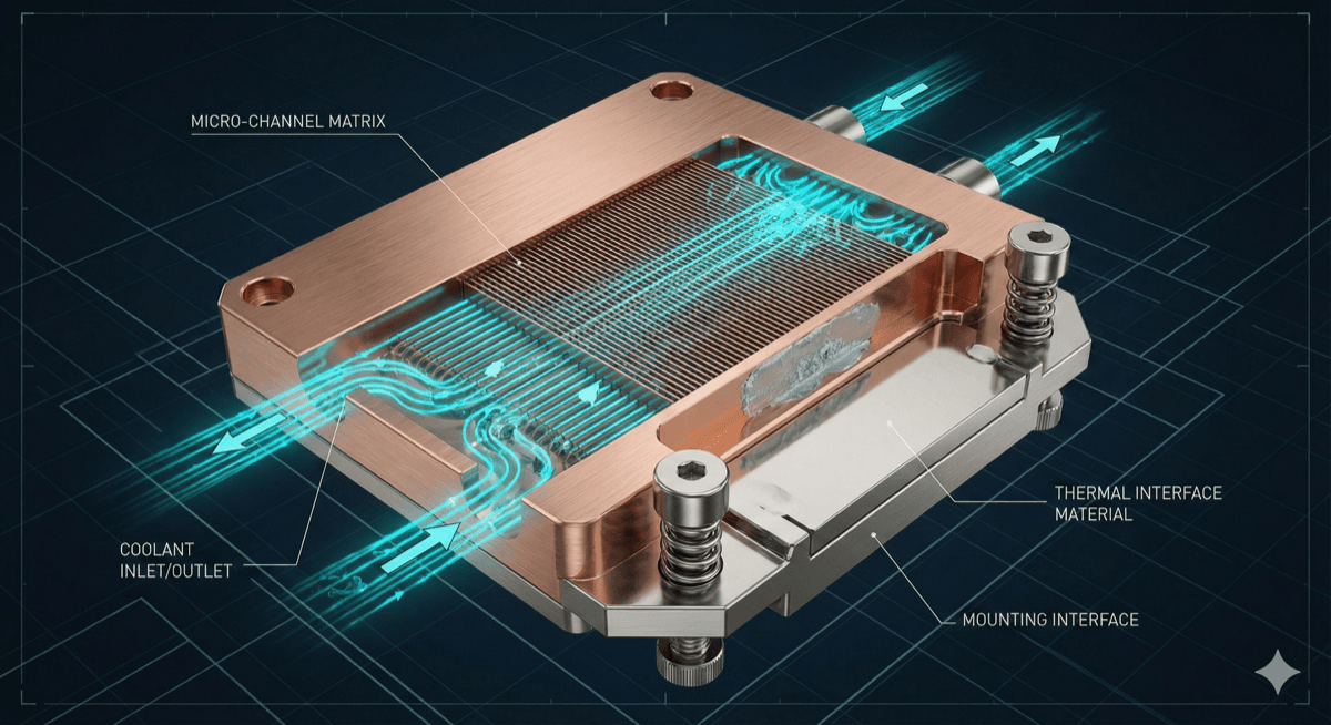
Cold Plate Design Principles
The cold plate is where liquid cooling's advantages are realized. Effective cold plate design requires balancing multiple factors:
Channel Geometry: Microchannel designs (channel widths of 100-500μm) provide the highest heat transfer coefficients but require significant pumping power. Mini-channel designs (1-3mm channels) offer a practical compromise for most applications.
Flow Distribution: Ensuring uniform flow across the cold plate surface is critical. Manifold design must prevent stagnant zones where local temperatures spike. CFD simulation is essential for optimizing flow distribution.
Pressure Drop: Lower pressure drop means smaller pumps and reduced parasitic power consumption. However, lower flow rates reduce heat transfer capability. The optimal operating point depends on system-level considerations.
Material Selection: Copper provides the best thermal conductivity but is expensive and heavy. Aluminum is adequate for many applications but requires careful attention to galvanic corrosion when mixed with copper components.
Surface Enhancement: Fins, pin arrays, and surface textures increase the effective heat transfer area. However, they also increase pressure drop and manufacturing complexity.
Mounting Interface: The interface between cold plate and GPU package is often the highest thermal resistance in the path. Design for adequate mounting pressure (typically 30-60 psi for thermal paste, less for gap pads), surface flatness (<0.05mm), and minimal contact thermal resistance.
A well-designed cold plate for GPU cooling achieves thermal resistance of 0.015-0.025°C/W, enabling 700W+ operation with reasonable coolant flow rates (0.5-1.0 L/min per GPU).

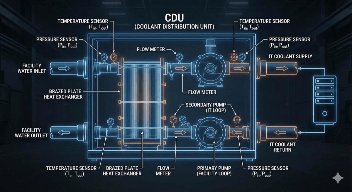
Coolant Distribution Units (CDUs)
The CDU is the heart of a liquid cooling system, transferring heat from the IT equipment loop to facility infrastructure. CDU design involves several key considerations:
Heat Exchanger Selection: Brazed plate, shell-and-tube, or gasketed plate heat exchangers each have advantages. Brazed plate offers compact size and good performance for most datacenter applications.
Flow Control: Variable-speed pumps enable energy optimization across varying loads. Flow sensors ensure adequate cooling even with partial system population.
Temperature Control: CDUs can operate in different modes:
- Constant supply temperature: Simplest control, may waste cooling capacity at low loads
- Load-following: Adjusts coolant temperature based on IT load for optimal efficiency
- Economizer mode: Uses facility water directly when conditions permit
Redundancy: Mission-critical deployments require N+1 or 2N redundancy. Quick-connect couplings enable CDU replacement without draining the IT loop.
Leak Detection: Rope-style leak detection cables, drip pans, and moisture sensors provide early warning of coolant leaks. Some systems include automatic isolation valves.
CDU sizing must account for future growth. IT loads in AI facilities can double within 2-3 years as accelerators are upgraded. Oversizing CDUs is generally preferable to early replacement.
Typical CDU specifications for AI deployments:
- Capacity: 50-500kW per unit
- IT loop temperature: 25-45°C supply
- Facility loop temperature: 15-35°C supply
- Pressure rating: 60-100 psi
- Flow rate: 50-500 GPM per unit
Facility Integration Challenges
Deploying liquid cooling in existing datacenters presents significant challenges. Even purpose-built facilities require careful planning:
Piping Infrastructure: Running chilled water to every rack requires extensive piping. Manifolds, isolation valves, and flexible hoses add complexity. Overhead vs. underfloor routing involves tradeoffs in accessibility, leak containment, and cost.
Weight Considerations: Water-filled systems are heavy. A fully populated liquid-cooled rack can exceed 4,000 lbs. Floor loading capacity, rack anchoring, and seismic considerations must be addressed.
Leak Containment: While modern liquid cooling systems have excellent reliability, leaks can occur. Containment strategies include:
- Drip trays under all liquid components
- Floor-level leak detection
- Sloped floors with drains in liquid-cooled zones
- Non-conductive coolants (with performance tradeoffs)
Maintenance Access: Quick-connect fittings enable hot-swap of servers and components, but require standardized protocols and training. Draining and refilling procedures must be documented.
Transition Strategy: Few facilities can convert entirely to liquid cooling overnight. Hybrid approaches—liquid cooling for AI workloads, air cooling for general compute—require careful thermal zone management.
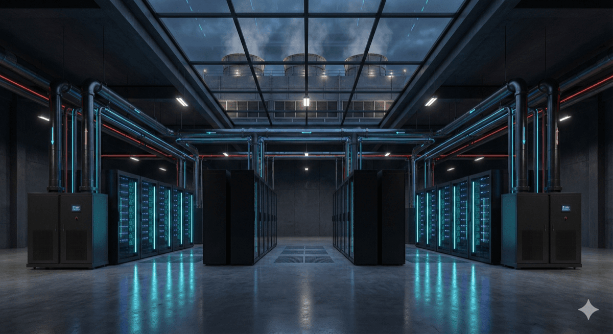
Heat Rejection: Facilities designed for air cooling may not have adequate heat rejection capacity for high-density AI loads. Adding cooling towers or dry coolers requires space, water rights, and structural support.
Power Delivery: Liquid cooling doesn't reduce electrical infrastructure requirements. If anything, higher rack densities concentrate power distribution challenges. PDUs, busways, and upstream electrical capacity must scale with IT load.
Operational Considerations
Running a liquid-cooled AI facility differs significantly from traditional datacenter operations:
Coolant Management: Propylene glycol mixtures are common for freeze protection and corrosion inhibition. Regular testing ensures proper concentration and pH levels. Contaminated coolant can foul heat exchangers and corrode components.
Filter Maintenance: Inline filters capture particles before they can damage pumps or clog microchannels. Filter differential pressure should be monitored and filters replaced on schedule.
Pump Reliability: Redundant pumps with automatic failover are essential. Pump failure can lead to GPU thermal shutdown within seconds. Vibration monitoring provides early warning of bearing wear.
Temperature Monitoring: Distributed temperature sensors throughout the cooling loop enable rapid detection of anomalies. Supply and return temperature differential indicates cooling effectiveness.
Leak Response: Despite precautions, leaks can occur. Response procedures must be practiced and documented:
- Automatic isolation of affected zones
- Emergency shutdown procedures
- Cleanup and damage assessment protocols
- Root cause analysis requirements
Capacity Planning: AI workloads are highly variable. Training runs may consume 100% of GPU capacity for weeks, then drop to near-zero between projects. Cooling systems must handle both extremes efficiently.
Training: Operations staff need specific training on liquid cooling systems. Many traditional datacenter skills don't transfer directly. Invest in training and maintain relationships with cooling system vendors for support.
Future Trends
Liquid cooling technology continues to evolve in response to AI demands:
Higher Temperature Operation: Warm water cooling (45°C+ supply) eliminates chillers and enables year-round free cooling. As component temperature ratings increase, expect wider adoption of warm water approaches.
Two-Phase Systems: Evaporative cooling provides extremely low thermal resistance. While still emerging for IT applications, two-phase systems may become practical as power densities continue to climb.
Integrated Rack Solutions: Pre-plumbed, pre-tested rack solutions reduce deployment complexity. Vendors like ZutaCore, CoolIT, and Vertiv offer turnkey systems.
AI-Optimized Facilities: Purpose-built AI datacenters are designed from the ground up for liquid cooling, with optimal piping layouts, adequate heat rejection, and specialized operational procedures.
Sustainability Focus: Liquid cooling's efficiency advantages align with growing sustainability mandates. Expect regulatory pressure and customer demand to accelerate liquid cooling adoption.
Standardization: Industry groups are developing standards for liquid cooling interfaces, coolant specifications, and system integration. This will reduce proprietary lock-in and enable multi-vendor deployments.
For organizations deploying AI infrastructure, liquid cooling is no longer optional—it's essential. The question is not whether to adopt liquid cooling, but how quickly and comprehensively to deploy it.