How to Size a Heat Sink for Power Electronics: Step-by-Step Guide

Properly sizing a heat sink is one of the most critical tasks in power electronics design. An undersized heat sink leads to thermal failures, while an oversized one wastes cost, weight, and space. This comprehensive guide walks you through the complete heat sink sizing process, from calculating thermal requirements to validating your design with simulation and testing.
Understanding the Thermal Resistance Network
Before selecting a heat sink, you need to understand the thermal path from your power semiconductor's junction to the ambient air. This path consists of several thermal resistances in series:
Junction-to-Case (Rth_jc): This is specified in the semiconductor datasheet. For a typical IGBT, it might be 0.1-0.5°C/W. This resistance is fixed by the device design.
Case-to-Sink (Rth_cs): This depends on the thermal interface material (TIM) you choose. Typical values:
- Thermal grease: 0.1-0.3°C/W
- Thermal pad: 0.3-1.0°C/W
- No TIM (metal-to-metal): 1.0-3.0°C/W
Sink-to-Ambient (Rth_sa): This is what you're trying to determine—the required heat sink thermal resistance.
The fundamental equation is: Tj = Ta + P × (Rth_jc + Rth_cs + Rth_sa)
Where:
- Tj = Junction temperature (°C)
- Ta = Ambient temperature (°C)
- P = Power dissipation (W)

Step 1: Determine Your Thermal Budget
Start by defining your constraints:
Maximum Junction Temperature (Tj_max): Check your semiconductor datasheet. Most power devices specify Tj_max of 150-175°C, but for reliability, derate by 20-30%. A design target of 100-125°C is common.
Maximum Ambient Temperature (Ta_max): Consider your worst-case operating environment:
- Indoor electronics: 40-50°C
- Outdoor/industrial: 50-60°C
- Under-hood automotive: 85-105°C
Power Dissipation (P): Calculate worst-case power loss in your semiconductor:
- Conduction losses: P_cond = I²×Rds_on (MOSFET) or Vce_sat×I (IGBT)
- Switching losses: P_sw = 0.5×V×I×(t_on + t_off)×f_sw
- Total: P_total = P_cond + P_sw
Example Calculation:
- Tj_max (derated) = 125°C
- Ta_max = 50°C
- P = 100W
- Rth_jc = 0.3°C/W
- Rth_cs = 0.2°C/W (with thermal grease)
Required Rth_sa = (Tj_max - Ta_max)/P - Rth_jc - Rth_cs Rth_sa = (125 - 50)/100 - 0.3 - 0.2 = 0.25°C/W
You need a heat sink with thermal resistance ≤0.25°C/W.
Step 2: Select Heat Sink Type and Size
Now you need to find a heat sink that achieves your required Rth_sa. Heat sink performance depends on:
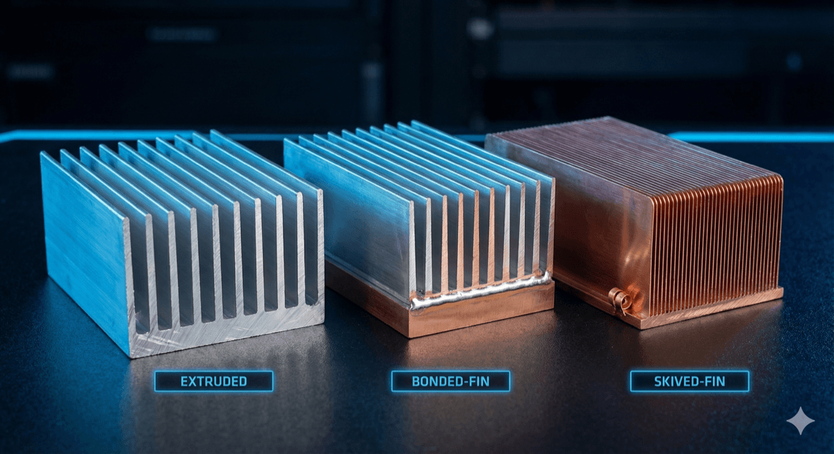
Heat Sink Types:
-
Extruded Aluminum: Most common, cost-effective for medium power. Typical Rth_sa: 0.5-5°C/W depending on size.
-
Bonded Fin: Higher performance for given footprint. Fins are bonded or brazed to base. Rth_sa: 0.1-1°C/W.
-
Skived Fin: Fine pitch fins cut from solid block. Excellent performance, higher cost. Rth_sa: 0.1-0.5°C/W.
-
Die-Cast: Complex shapes possible, good for high volume. Performance varies widely.
-
Liquid-Cooled Cold Plates: For very high power density. Rth_sa equivalent: 0.01-0.1°C/W.
Selection Process:
-
Calculate required heat sink surface area as a starting point: A ≈ P / (h × ΔT) Where h ≈ 10-25 W/m²K for natural convection, 50-150 W/m²K for forced air
-
Search heat sink catalogs for products matching your footprint and Rth_sa requirements
-
Consider mounting constraints—does the heat sink base match your component layout?
-
Account for altitude derating if applicable (air density decreases ~12% per 1000m)
Step 3: Account for Forced Air Cooling
If natural convection doesn't provide adequate cooling, you'll need forced air. Heat sink datasheets typically provide Rth_sa at multiple airflow velocities.
Airflow Velocity Estimation: For a fan blowing across a heat sink: V = CFM / (60 × A_flow)
Where:
- V = air velocity (ft/s or m/s)
- CFM = fan airflow rating
- A_flow = cross-sectional flow area (ft² or m²)
Important Considerations:
-
System Impedance: The actual airflow through your heat sink depends on system pressure drop. A "200 CFM" fan might only deliver 50 CFM in a constrained enclosure.
-
Fan Curve: Use the fan's pressure-flow curve to determine actual operating point based on system impedance.
-
Velocity Profile: Air velocity varies across the heat sink. Center channels typically see higher velocity than edges.
-
Temperature Rise: Air temperature increases as it passes through the heat sink. Account for this in your calculations.
Rule of Thumb: Forced air at 2-3 m/s typically reduces Rth_sa by 40-60% compared to natural convection.
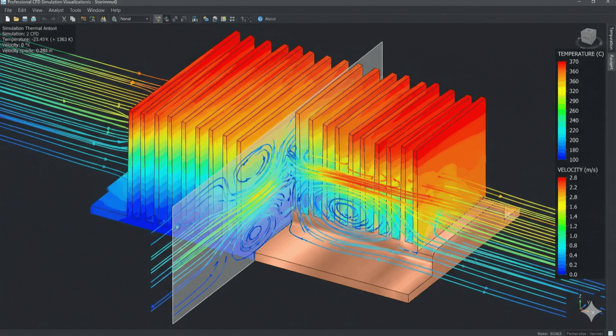
Step 4: Validate with CFD Simulation
Analytical calculations provide a starting point, but CFD simulation is essential for optimizing your design and catching problems early.
What CFD Reveals:
- Hot Spots: Localized temperature peaks that analytical methods miss
- Flow Distribution: How air actually flows through your heat sink (often different from assumptions)
- Thermal Coupling: How multiple heat sources interact
- Transient Behavior: Temperature response during power cycling
Simulation Best Practices:
-
Model Setup:
- Include all significant heat sources, not just the main component
- Use accurate material properties (temperature-dependent if needed)
- Model TIM layers explicitly—they significantly impact results
-
Boundary Conditions:
- Apply realistic inlet conditions (temperature, velocity profile)
- Don't forget radiation, especially for natural convection
- Consider solar loading for outdoor equipment
-
Mesh Quality:
- Use inflation layers on all solid-fluid interfaces
- Refine mesh in regions with high temperature gradients
- Perform mesh independence study
-
Validation:
- Always compare simulation to thermal measurements
- Adjust contact resistances and boundary conditions to match data
- Document assumptions and validation results
Step 5: Prototype Testing and Validation
CFD gets you close, but nothing replaces physical testing to validate your thermal design.
Testing Methods:
-
Thermocouple Measurements:
- Place thermocouples at critical locations (component cases, heat sink base, air inlet/outlet)
- Use thermal paste to ensure good contact with surfaces
- Allow system to reach steady state (typically 30-60 minutes)
-
Thermal Imaging:
- Reveals temperature distribution across surfaces
- Good for identifying hot spots and flow patterns
- Requires knowledge of surface emissivity for accurate readings
-
Power Cycling Tests:
- Simulate actual operating profiles
- Verify thermal time constants match predictions
- Identify any thermal ratcheting or progressive degradation
Test Conditions:
- Test at worst-case ambient (use environmental chamber if needed)
- Apply worst-case power dissipation
- If using fans, test at end-of-life airflow (fans degrade over time)
- Run for sufficient time to reach thermal equilibrium
Acceptance Criteria:
- All junction temperatures within limits with margin
- Temperature distribution matches simulation predictions (±10-15%)
- No unexpected hot spots or flow problems
- Thermal time constants appropriate for application
Common Heat Sink Sizing Mistakes
Learn from these frequent errors:
1. Using Datasheet Rth_sa Directly: Heat sink datasheets often specify Rth_sa under ideal conditions (uniform heat source, optimal orientation, specific airflow). Real-world performance may be 20-50% worse.
2. Ignoring Spreading Resistance: If your heat source is much smaller than the heat sink base, thermal spreading resistance can be significant. A small die on a large heat sink doesn't use the full fin area effectively.
3. Forgetting Interface Resistance: The TIM layer often contributes 0.1-0.5°C/W to the thermal path. This can be 10-50% of your thermal budget.
4. Assuming Linear Scaling: Doubling heat sink size doesn't halve thermal resistance. Returns diminish as size increases.
5. Neglecting Altitude Effects: At high altitude, reduced air density degrades both natural and forced convection. Derate heat sink performance accordingly:
- 3000m (10,000 ft): ~25% reduction
- 5000m (16,000 ft): ~40% reduction
6. Optimistic Airflow Assumptions: System airflow is almost always less than free-air fan ratings. Use system-level CFD or testing to determine actual airflow.
7. Ignoring Transient Requirements: Steady-state calculations don't capture temperature spikes during power transients. Verify thermal mass is adequate for your duty cycle.
Free Resource: Download our Thermal Design Checklist — an 8-page checklist covering all critical thermal design considerations for power electronics.