DFM Guidelines for Sheet Metal Enclosures
Sheet metal enclosures house the majority of industrial power electronics, from small VFDs to large-scale energy storage inverters. While conceptually simple—bend some metal, add fasteners, call it done—designing sheet metal enclosures that are cost-effective, manufacturable, and reliable requires attention to numerous DFM (Design for Manufacturability) principles. This guide covers the essential rules that separate elegant, production-ready designs from those that cause manufacturing headaches and cost overruns.
Understanding Sheet Metal Manufacturing
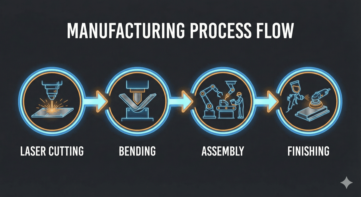
Before diving into specific rules, it's important to understand the basic manufacturing processes:
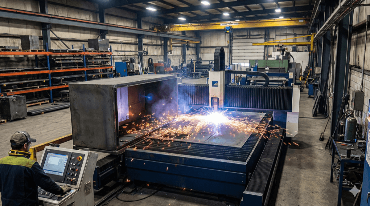
Laser/Punch Cutting: Flat sheet metal is cut to shape using laser cutters (most common for precision work) or turret punch presses (efficient for high volumes with standard hole patterns). Lasers can cut complex contours while punches are limited to the shapes of available tooling.
Bending: Press brakes form sheet metal into three-dimensional shapes by pressing it between a punch and die. Each bend is formed sequentially, with part geometry constrained by the press brake's throat depth and tooling clearances.
Forming: Additional operations like countersinks, louvers, embossments, and drawn features are created using specialized tooling. These add cost but enable functional features impossible with simple bends.
Joining: Parts are assembled using fasteners (screws, rivets, PEM inserts), welding (spot, MIG, TIG), or adhesives. Each method has trade-offs in cost, strength, and appearance.
Finishing: Surface treatments including powder coating, anodizing, zinc plating, or chromate conversion provide corrosion protection and aesthetic finish.
Material Selection
Material choice affects cost, manufacturability, corrosion resistance, and EMC performance:
Cold Rolled Steel (CRS) The most economical option for indoor applications. Excellent formability and weldability. Requires paint or plating for corrosion protection. Common thicknesses: 0.8-2.0mm.
Galvanized Steel Pre-coated with zinc for corrosion resistance. Suitable for moderate outdoor exposure. The zinc coating can complicate welding and may require special primers before painting. Avoid specifying galvanized steel for exposed outdoor applications—hot-dip galvanizing or stainless steel is more appropriate.
Aluminum Lighter than steel (about 1/3 the density) with inherent corrosion resistance. More expensive and requires larger bend radii. Excellent for outdoor applications and products where weight matters. Common alloys: 5052 (best formability), 6061 (good for machined features).
Stainless Steel Superior corrosion resistance for harsh environments. Significantly more expensive and more difficult to form and weld than carbon steel. Common grades: 304 (general purpose), 316 (marine/chemical environments).
Standard thickness gauges (10, 12, 14, 16, 18, 20 ga) are more economical than custom thicknesses due to material availability.
Bend Design Rules
Proper bend design is fundamental to sheet metal DFM:
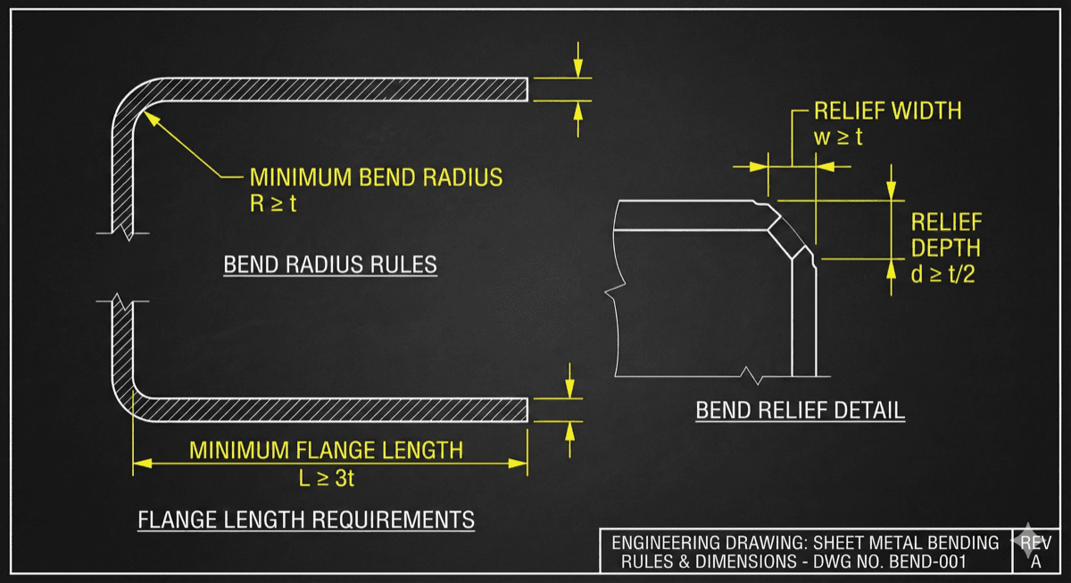
Minimum Bend Radius Inside bend radius should be at least equal to material thickness for steel, 1.5-2x thickness for aluminum. Tighter radii risk cracking, especially on harder materials or across the grain direction.
Minimum Flange Length The flat portion adjacent to a bend must be at least 4x material thickness, or the material will deform unpredictably. Account for this when designing small tabs or flanges.
Bend Relief When a bend terminates at an edge, add a relief cut (at least material thickness wide) to prevent tearing. Without relief, the material adjacent to the bend will tear or bulge.
Minimum Distance Between Bends Parallel bends should be separated by at least 8x material thickness to allow tooling clearance. For opposed bends (forming a U-channel), consider whether the part can be physically loaded into the press brake.
Bend-to-Hole Spacing Holes too close to bends will deform when the bend is formed. Maintain at least 3x material thickness plus the bend radius between hole edges and bend lines.
Bend-to-Edge Distance Keep bends at least 4x material thickness from part edges to ensure consistent forming. Material too close to edges may not be adequately constrained during bending.
Hole and Cutout Design
Holes and cutouts have their own set of DFM considerations:
Minimum Hole Size Laser cutting can produce holes as small as material thickness. Punching typically requires minimum hole diameter of 1.5x thickness. Smaller holes may require secondary drilling or special tooling.
Hole Spacing Maintain at least 2x material thickness between holes, and between holes and edges. Closer spacing can cause material distortion during cutting or subsequent forming.
Avoid Sharp Internal Corners Laser-cut parts can have sharp corners, but internal corners with less than 0.5mm radius concentrate stress and are prone to cracking. Add small radius fillets (0.5-1mm) to internal corners of cutouts.
Slot Design Slots should have width at least equal to material thickness and end radii equal to half the slot width. Very narrow slots are difficult to cut cleanly and may distort during forming.
Countersinks and Counterbores These features require secondary operations and add cost. Where possible, use through-holes with standard screws and nuts rather than requiring counterbores for socket head cap screws.
Grain Direction Material properties vary with grain direction. Bends across the grain are stronger and less prone to cracking than bends along the grain. For critical applications, specify grain direction on drawings.
Assembly Considerations
How parts fit together significantly impacts manufacturing cost and assembly time:
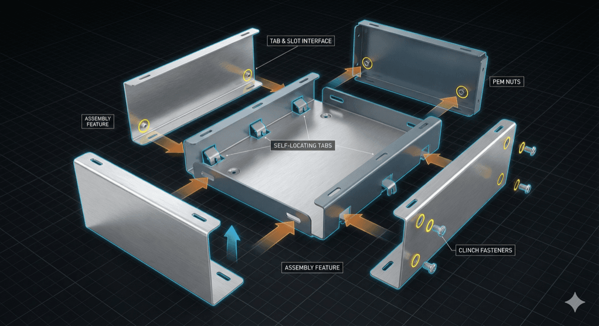
Self-Locating Features Design parts with tabs, slots, and embossments that automatically align components during assembly. This reduces fixture requirements and makes hand assembly faster and more consistent.
Fastener Access Ensure adequate clearance for tools to install fasteners. Nothing frustrates assembly technicians more than screws they can't reach. Provide at least 10mm clearance around screw heads for manual tools, more for power tools.
PEM Hardware Threaded inserts (PEM nuts, studs, standoffs) installed during fabrication eliminate loose hardware during assembly. Specify standard PEM hardware sizes (M3, M4, M5) to minimize inventory requirements.
Weld Access If welding is required, ensure welders can access the joint with appropriate equipment. MIG/TIG welding requires more clearance than spot welding. Specify weld types and locations clearly on drawings.
Tolerances Sheet metal tolerances are relatively loose—typically ±0.25-0.5mm for cut features and ±0.5-1° for bends. Design interfaces with adequate clearance rather than tight tolerances that increase cost.
Assembly Sequence Consider how the product will be assembled. Design should allow a logical build sequence without requiring disassembly of previously-installed components to add others.
Finishing and Protection
Surface finishing protects against corrosion and provides aesthetic quality:
Powder Coating The most common finish for industrial enclosures. Durable, available in many colors, and cost-effective for large parts. Typical thickness: 60-80μm. Ensure adequate hanging/grounding points for the coating process.
Wet Paint More expensive than powder coating but offers finer control over appearance. Required for temperature-sensitive plastics or components that can't withstand powder coating cure temperatures (typically 180-200°C).
Anodizing (Aluminum Only) Electrochemical process that creates a hard, corrosion-resistant oxide layer. Available in clear or colored versions. Type II (decorative) is 10-25μm; Type III (hard) is 25-75μm. Excellent for outdoor applications.
Plating (Steel) Zinc plating provides economical corrosion protection. Yellow zinc chromate offers better corrosion resistance than clear zinc. For severe environments, consider zinc-nickel plating.
Gasket and Seal Surfaces For IP-rated enclosures, ensure sealing surfaces are flat and free from weld spatter or distortion. Specify surface flatness requirements on critical sealing areas.
Cost Reduction Strategies
Smart design choices can significantly reduce manufacturing cost:
Standardize on Common Features Use consistent hole sizes, bend radii, and hardware throughout the design. This reduces tooling changes and simplifies procurement.
Minimize Secondary Operations Each additional operation (countersinking, tapping, forming) adds cost. Challenge whether each feature is truly necessary.
Optimize Nesting Work with manufacturers to optimize how parts nest on standard sheet sizes. Irregular shapes or odd dimensions may result in poor material utilization.
Design for Volume For high-volume production, consider progressive die tooling that combines cutting and forming in a single operation. Initial tooling cost is high but per-part cost is significantly reduced.
Eliminate Tight Tolerances Every tolerance tighter than standard manufacturing capability adds cost through slower processing, inspection requirements, and yield losses. Specify only the tolerances actually required for function.
Consider Alternative Processes For complex shapes or high volumes, die casting or injection-molded plastic may be more economical than fabricated sheet metal. Evaluate alternatives during the design phase.
Free Resources: Download our DFM Red Flags Guide to avoid the 12 most common manufacturing issues, and our Sheet Metal Design Rules for comprehensive DFM guidelines.